

PET Blow Mould Cooling and Venting Checks Before a Trial
PET blow mould cooling removes heat through the tool, while venting lets air escape from the cavity as the bottle expands. Check both before raising pressure or extending the cycle. A restricted water circuit can leave the base unstable after release; a blocked vent can prevent a local detail from forming even when the pressure setting looks correct.
The following checks apply mainly to conventional reheat stretch blow moulding with cooled tooling. Heat-set and hot-fill processes use different thermal arrangements. BJY‘s technical notes distinguish mould thermal control from bottle exhaust and identify base cooling and vent condition as troubleshooting factors. Keep those functions separate when discussing a new mould or a recurring defect.
Follow the water path and the air path separately
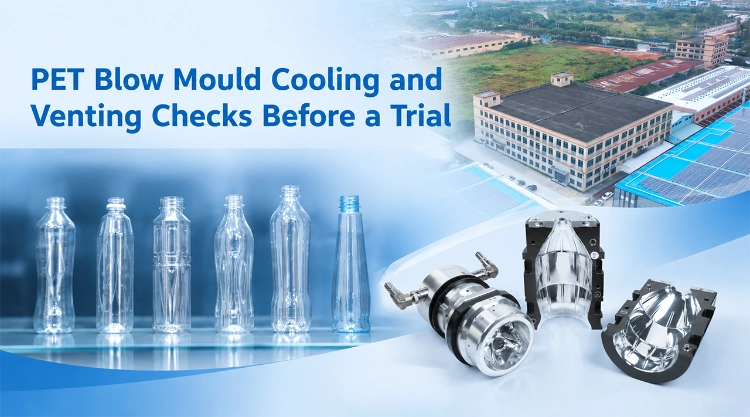
The cooling circuit carries heat away through the mould assembly. The cavity vent path carries displaced air away from the outside of the expanding bottle. Air released from inside the bottle at the end of the cycle uses the machine’s exhaust system. These paths have different jobs and should have separate entries on the inspection sheet.
BJY’s defect notes list blocked base vents among the possible causes of incomplete base formation. They also associate abnormal mould cooling-water circulation with base problems. Neither observation proves that every poorly formed foot is a mould defect. Heating, rod position, pressure and timing still need to be considered.
Begin with labelled samples from the affected station and a known acceptable station. Record whether the defect appears immediately after startup, after continued running or following a mould change. That history helps choose the first check without treating a single photograph as a diagnosis.
Verify water circulation at the mould
Check the circuit beyond the chiller display
A chiller setpoint does not tell you whether water reaches every circuit as intended. Identify the supply and return connections on the approved drawing, then compare the installed arrangement. Check hoses, couplings and valve positions under the plant’s maintenance procedure. Do not disconnect or open a pressurised circuit for inspection.
BJY’s technical guidance identifies bottom cooling-water flow as a relevant check when base cooling is poor. Measure the available flow and temperatures at repeatable locations, where the installation allows it, and compare them with the approved process. A temperature difference by itself is not a complete diagnosis: flow and heat load matter too.
If one station behaves differently, inspect its local circuit before changing the common water supply for the whole machine. Record a restricted coupling or incorrect hose connection as a finding, then rerun the trial after correction. Changing the chiller setting at the same time would obscure which action mattered.
Give the base its own inspection
The bottle base deserves a separate line on the checklist. BJY’s main knowledge base discusses bottom-mould cooling-channel design and links poor base cooling with unstable bottom geometry. It also notes that the amount of material in the bottom matters; a base that is too thick or too thin is not automatically satisfactory.
Compare the actual base insert and its connections with the drawing. Check whether the base circuit is independent or shared on this particular tool, and how its performance will be measured. Do not assume that acceptable cavity-body cooling proves acceptable base cooling.
Record base shape after a consistent interval following discharge. If bottles stand correctly at first and then lose stability, preserve those samples and their times. They are more useful than a photograph taken at an unknown point in cooling. Compare the result with the specified base dimensions and standing requirements.
Inspect venting where the detail fails
Look for a repeated location
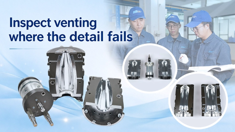
When the same small feature fails repeatedly in one cavity, compare that location with the venting drawing. BJY’s 350ml PET Blow Mold description identifies venting at the parting line and base inserts, with an outlet path behind the vents. That is a useful example of the details to request from a supplier.
Check the full intended route, not only the visible opening. Air needs somewhere to go after entering the vent. Photograph the affected area and document any residue, damage or obstruction that a qualified technician finds. If the path is clear, return to the other causes of incomplete forming rather than enlarging the vent on assumption.
BJY’s defect guidance also lists insufficient high-pressure air, a cool base region, short high-pressure blowing time and late preblow for incomplete base formation. Venting is one branch of the investigation. The symptom alone cannot tell you which branch is responsible.
Clean to the drawing and maintenance instructions
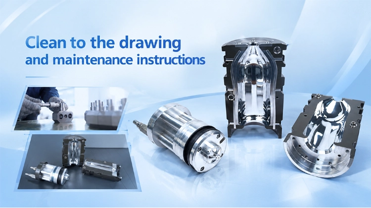
Vent geometry is part of the tool design. Ask for the approved cleaning method and inspection criteria before maintenance begins. Do not drill, deepen or scrape a vent to an improvised size. A visible improvement in air escape would not establish that the altered mould remains within its drawing.
Keep before-and-after photographs and record which passage was cleaned. Use the same starting process to assess the result. If several vents need repeated attention, discuss access and maintenance frequency with the supplier; do not hide the pattern by recording every event as a general cleaning job.
The 500ml PET Blow Mold Cavity is another specific reference, with an aluminium body, stainless-steel inserts and parting-line venting. Compare the relevant construction with the application. Its published features are not a guarantee that the same geometry will suit a different bottle.
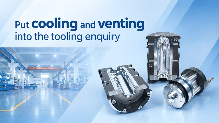
Put cooling and venting into the tooling enquiry
A request for a PET bottle mould should include more than bottle volume. Supply the approved bottle drawing, preform details, machine identification and the cavity-to-holder interface. Add the actual utility conditions and explain whether the question concerns new tooling, a replacement base or a defect on an existing mould.
BJY’s product material describes aluminium tooling and designed cooling channels as means of managing heat transfer. Its main technical notes also describe a separable cavity and bottom-mould arrangement for maintenance. Ask which construction is proposed for your project, what remains accessible after installation and which components can be inspected separately.
For formats beyond the two product examples, the PET blowing mould range is a starting point for identifying possible tooling. Obtain confirmation against the machine drawing. Matching nominal capacity does not confirm hose clearance, port location, insert seating or the mounting interface.
A useful enquiry includes these practical questions:
- Where are the supply, return and vent outlets on the proposed assembly?
- Which checks establish that each cooling circuit is functioning?
- Which passages can be cleaned without altering the cavity geometry?
- What samples and measurements will decide trial acceptance?
Run a trial that separates the possible causes
Choose a stable baseline and identify the fault before making changes. If the first finding is a water-flow restriction, correct and record that condition before altering pressure. If the first finding is an obstructed vent, assess the cleaned tool with the previous approved settings where safe and appropriate.
BJY’s parameter guidance recommends changing one variable at a time and maintaining adjustment records. It also calls for mechanical inspection if faults continue. That approach applies just as well to a cooling or venting investigation: do not use a longer cycle to conceal an unresolved local defect.
Collect samples across the relevant stations and after continued running under an agreed sampling plan. Check the original symptom alongside the bottle specification. Depending on the application, acceptance may include dimensions, section weights, leak performance, standing stability and required load or pressure tests. Set the limits before seeing the best samples.
Send BJY the circuit drawing, labelled defect photographs and the trial measurements when requesting a tooling review. State what was changed and what stayed fixed. That gives the supplier a basis for discussing waterway design, vent access or another cause without promising that a new mould alone will solve the problem.
Questions about cooling and venting
Will colder water always improve the bottle?
No. First confirm circulation and the approved thermal conditions for the actual process. A restricted circuit still needs attention, and heat-set tooling requires a different thermal strategy. Judge changes by stable bottle performance rather than the lowest available setpoint.
Can a bigger vent replace higher blowing pressure?
There is no general substitution rule. Internal pressure and cavity venting perform different functions. Confirm the cause of the defect and have the mould supplier assess any geometry change against the drawing before modifying the tool.
Can shared cooling circuits for multiple cavities lead to inconsistent bottle quality?
Yes. If several cavities share one cooling water loop, blockages, kinked hoses or valve faults may cause uneven flow across individual mould stations. Even if the chiller reading looks normal, one cavity could suffer insufficient cooling. Always check flow and temperature readings per‑cavity where possible, rather than only checking the overall main water supply.